MIPI DSI Display Driver
Introduction
Section titled “Introduction”This driver is for displays that use the MIPI DSI display interface available in the ESP32-P4.
Background
Section titled “Background”The MIPI (Mobile Industry Processor Interface) Alliance publishes various hardware and software interface specifications including the Display Serial Interface (DSI), which transfers pixel data over a high-speed serial bus to an LCD display.
The display panels controlled by the driver may be of various types, including TFT, IPS, and others. Each driver chip and panel combination requires a specific set of initialisation commands, and standard initialisation sequences are provided for many common boards and chips, but the driver is also designed to be customisable in YAML for other displays.
Supported driver chips, display panels and boards
Section titled “Supported driver chips, display panels and boards”Driver chips
Section titled “Driver chips”For custom displays, the driver can be configured with the correct pins and dimensions, and the driver chip can be specified, or a custom init sequence can be provided.
| Driver Chip | Typical Dimensions |
|---|---|
| CUSTOM | Customisable |
Standalone displays
Section titled “Standalone displays”These are standalone display panels incorporating a driver chip and display panel. The transform, rotation, or other
layout parameters may need to be specified to suit a specific usage scenario. These displays typically do not
physically expose reset or enable pins but they may have a connector for an I²C bus for a touchscreen or to
control the backlight. Check the manufacturer’s documentation for information on how to use them.
Some of these displays are used by ESP32 boards defined in the next section.
| Model | Manufacturer | Dimensions | Product Link |
|---|---|---|---|
| WAVESHARE-10.1-DSI-TOUCH-A | Waveshare | 800x1280 | 10.1-DSI-TOUCH-A product page |
| WAVESHARE-8-DSI-TOUCH-A | Waveshare | 800x1280 | 8-DSI-TOUCH-A product page |
| WAVESHARE-7-DSI-TOUCH-A | Waveshare | 720x1280 | 7-DSI-TOUCH-A product page |
| WAVESHARE-4-DSI-TOUCH-C | Waveshare | 720x720 (round) | 4-DSI-TOUCH-C product page |
| WAVESHARE-3.4-DSI-TOUCH-C | Waveshare | 800x800 (round) | 3.4-DSI-TOUCH-C product page |
Boards with integrated displays
Section titled “Boards with integrated displays”These are specific configurations for several ESP32 boards with integrated displays. The predefined configuration will set the correct pins and dimensions for the display.
| Model | Manufacturer | Product Link |
|---|---|---|
| JC1060P470 | Guition | JC1060P470 product page |
| JC4880P443 | Guition | JC4880P443 product page |
| JC8012P4A1 | Guition | JC8012P4A1 product page |
| M5STACK-TAB5 | M5Stack | TAB5 product page |
| M5STACK-TAB5-V2 | M5Stack | TAB5-V2 product page |
| WAVESHARE-P4-NANO-10.1 | Waveshare | P4-NANO-10.1 product page |
| WAVESHARE-P4-86-PANEL | Waveshare | P4-86-PANEL product page |
| WAVESHARE-ESP32-P4-WIFI6-TOUCH-LCD-7B | Waveshare | P4-WIFI6-TOUCH-LCD-7B product page |
| WAVESHARE-ESP32-P4-WIFI6-TOUCH-LCD-3.4C | Waveshare | P4-WIFI6-TOUCH-LCD-3.4C product page |
| WAVESHARE-ESP32-P4-WIFI6-TOUCH-LCD-4C | Waveshare | P4-WIFI6-TOUCH-LCD-4C product page |
NOTE
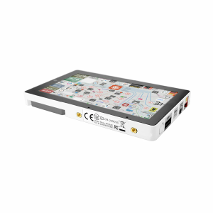
The M5Stack Tab5 has two hardware revisions with different display chips requiring different model selections.
Units manufactured before October 14, 2025 use the ILI9881C display driver with separate GT911 touch driver (use M5STACK-TAB5).
Units manufactured on or after that date use the integrated ST7123 display-touch driver (use M5STACK-TAB5-V2).
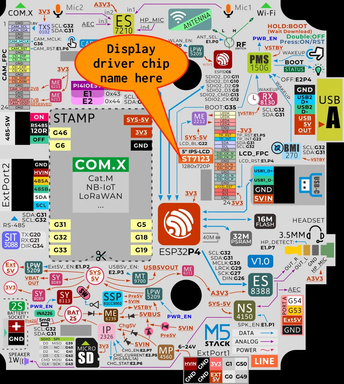
If unsure which model you have, check the sticker on the back of the device for the display driver chip name. The label is just above the ESPressif icon. See image below for example of V2 hardware.
Selection of the wrong display driver model will cause the display to simply fail to work with no relevant logging. Selection of the wrong touchscreen driver however will display an error message in the log output, so if in doubt, verify the correct touchscreen driver first to accurately identify the board before configuring the display driver.
Configuration
Section titled “Configuration”# Example minimal configuration entrydisplay: - platform: mipi_dsi model: WAVESHARE-P4-NANO-10.1Configuration options
Section titled “Configuration options”All graphical display configuration options are available, plus the following. For integrated display boards most of the configuration will be set by default, but can be overridden if needed.
-
model (Required): Chosen from the lists of supported chips and models above, or
CUSTOMfor custom displays. -
reset_pin (Optional, Pin Schema): The RESET pin, if required.
-
enable_pin (Optional, Pin Schema): An optional pin to enable the display, if required. A list of pins can be provided for displays that require multiple enable pins. A full pin configuration may be provided to set the pin mode and inverted property. By default the pin will be driven high to enable the display.
-
color_order (Optional): Should be one of
bgr(default) orrgb. This specifies the order of the color channels in the display panel. The default isbgrfor most displays, but some displays may requirergb. It does not affect the color order of the display buffer, which is always RGB. -
dimensions (Optional): Dimensions of the screen, specified either as width x height (e.g
320x240) or with separate config keys. If not provided the dimensions will be determined by the model selected. This is required for theCUSTOMmodel, and is optional for other models. The dimensions are specified in pixels, and the width and height must be greater than 0. The following keys are available:- height (Required, int): Specifies height of display in pixels.
- width (Required, int): Specifies width of display.
- offset_width (Optional, int): Specify an offset for the x-direction of the display, typically used when an LCD is smaller than the maximum supported by the driver chip. Default is 0
- offset_height (Optional, int): Specify an offset for the y-direction of the display. Default is 0.
-
invert_colors (Optional, boolean): Specifies whether the display colors should be inverted. Options are
trueorfalse. Defaults tofalse. -
rotation (Optional): Rotate the display presentation in software. Choose one of
0°,90°,180°, or270°. If the driver chip supports hardware rotation for the given orientation this will be translated to the appropriate hardware command. If hardware rotation is not supported, the display will be rotated in software. -
transform (Optional): If
rotationis not sufficient, use this to transform the display. If this option is specified, then thedimensionsoption must also be provided. The value can either be the stringdisabledto disable hardware transform, or a dictionary. For theCUSTOMmodel, usetransform: disabledif the display does not support it, which will prevent arotationbeing translated to a hardware transform, otherwise the options below. Note that DSI displays do not support axis swapping so only mirroring of x and y axes is possible, and rotations by 90 or 270 must be handled by software.- mirror_x (Required, boolean): If true, mirror the x axis.
- mirror_y (Required, boolean): If true, mirror the y axis.
-
hsync_pulse_width (Optional, int): The horizontal sync pulse width.
-
hsync_front_porch (Optional, int): The horizontal front porch length.
-
hsync_back_porch (Optional, int): The horizontal back porch length.
-
vsync_pulse_width (Optional, int): The vertical sync pulse width.
-
vsync_front_porch (Optional, int): The vertical front porch length.
-
vsync_back_porch (Optional, int): The vertical back porch length.
-
pclk_frequency (Optional): Set the pixel clock speed. Default is 40MHz.
-
pclk_inverted (Optional, bool): If the pclk is active negative (default is True)
-
lanes (Optional, int): Number of serial data lanes to use - 1 or 2. Default is 2.
-
lane_bit_rate (Optional, int): The bit rate of the serial data lanes. No default unless a non-custom model is selected.
Advanced options
Section titled “Advanced options”- init_sequence (Optional): Allows custom initialisation sequences to be added. See below for more information.
- pixel_mode (Optional): Select the interface mode for the display driver. Options are
16bit(default) and24bit. - color_depth (Optional): The color depth of the display buffer, expressed in bits. Options are
16(default) and24. Preferably should be the same as thepixel_modeoption. - draw_rounding (Optional): The rounding factor for drawing operations. Defaults to 2. Some chips require a higher value to avoid display artifacts. Must be a power of 2.
- use_axis_flips (Optional): If true, the driver will use alternate bits in the MADCTL register to implement x and y mirroring. Defaults to false.
- byte_order (Optional): The byte order of the display buffer. Options are
big_endianandlittle_endian(default). This affects the byte order for the buffer when using 16 bit color depth. The default is appropriate for the majority of displays.
Additional initialisation sequences
Section titled “Additional initialisation sequences”The init_sequence option allows additional configuration of the driver chip. Provided commands will be sent to the
driver chip in addition to, and after the chosen model’s pre-defined commands. It requires a list of byte sequences:
init_sequence: - [ 0xD0, 0x07, 0x42, 0x18] - delay 10ms - [ 0xD1, 0x00, 0x07, 0x10]Each entry represents a single-byte command followed by zero or more data bytes. Delays can be inserted with the delay keyword followed by a time in milliseconds. The delay is not precise, but will be at least the specified time.
If converting from other code, make sure the length byte, if present, is not copied as the length of each command sequence is determined by the number of bytes in the list.
CUSTOM model
Section titled “CUSTOM model”The CUSTOM model selection is provided for otherwise unsupported displays, and requires both dimensions: and init_sequence: to be specified. There is no pre-defined init sequence.
Using the transform options
Section titled “Using the transform options”In most cases, the rotation option will be sufficient to orient the display correctly. However, some displays may require additional transformations such as mirroring the x or y axes, which is accomplished with the transform: option.
transform: mirror_x: true mirror_y: falserotation: 90LCD Backlights
Section titled “LCD Backlights”Many displays have an integrated backlight, which may need to be turned on for the display to show. This backlight is not controlled by the driver, but can be controlled by a separate GPIO pin. Depending on the display, the backlight may be active high or active low, and may be able to be dimmed using a Monochromatic with a Ledc.
Touchscreens
Section titled “Touchscreens”A touchscreen, if present, must be configured separately. See the Touchscreen documentation for more information.