

LD2460 Sensor
Component
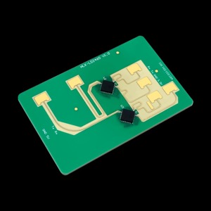
Section titled “Component”The ld2460 component allows you to use the Hi-Link HLK-LD2460 24GHz 2T4R millimeter-wave radar module with
ESPHome. The module is made by Hi-Link (vendor website).
The LD2460 is an intelligent multi-target trajectory tracking sensor module. It can simultaneously detect and track the trajectory and position of up to 5 moving human targets in real-time, measuring distance, angle, and 2D planar coordinates ().
The component currently offers the sensor platform only.
- HLK-LD2460 serial protocol V1.0 (English translation)
- HLK-LD2460 manuals and protocol on the vendor’s Google Drive
The UART bus must be configured for communication, with both the TX and RX pins connected.
Use of a hardware UART is recommended. The default baud rate of the LD2460 module is 115200 with 8 data bits,
no parity, and 1 stop bit.
# Example configuration entryld2460: id: ld2460_radarConfiguration Variables
Section titled “Configuration Variables”- id (Optional, ID): Manually specify the ID for this LD2460 component.
- uart_id (Optional, ID): Manually specify the ID of the UART Component to use. Required if multiple UARTs are configured.
- on_data (Optional, Automation): An action or automation to perform after each report frame is received and decoded. It passes no variables. The module sends report frames continuously, so this runs very often; keep the automation short.
ld2460: id: ld2460_radar on_data: then: - logger.log: "Frame received"Sensor
Section titled “Sensor”The ld2460 sensor platform exposes the target count and real-time tracking data for up to 5 detected targets.
sensor: - platform: ld2460 ld2460_id: ld2460_radar target_count: name: "Target Count" target_1: x: name: "Target 1 X" y: name: "Target 1 Y" distance: name: "Target 1 Distance" angle: name: "Target 1 Angle" # target_2 to target_5 follow the same shapeConfiguration Variables
Section titled “Configuration Variables”- ld2460_id (Optional, ID): Manually specify the ID of the parent LD2460 component. Required if multiple LD2460 components are configured.
- target_count (Optional): Total number of targets currently detected (0 to 5). All options from Sensor.
- target_1, target_2, target_3, target_4, target_5 (Optional): Tracking data for one target.
Each accepts the following sensors:
- x (Optional): Position in meters across the face of the module (left and right), in 0.1 m steps. Negative values are to the left, positive values to the right. All options from Sensor.
- y (Optional): Position in meters along the module’s forward axis, in 0.1 m steps. The module reports it as a signed value: positive in front of a side-mounted module, and either sign across the floor under a top-mounted one. All options from Sensor.
- distance (Optional): Straight-line distance from the radar to the target () in meters. All options from Sensor.
- angle (Optional): Target angle in degrees. All options from Sensor.
When a target is no longer tracked, its sensors report an unknown state.
Target Angle
Section titled “Target Angle”The way the angle is calculated depends on how the module is mounted. The component reads the installation mode from the module at boot:
- Side (wall mounted): 0° is straight out from the module (along +Y) and positive angles are towards +X. The range is about -90° to 90°.
- Top (ceiling mounted): 0° is along +X and the angle increases towards +Y. The range is 0° to 360°.