

CC1101 Low-Power Sub-1 GHz RF Transceiver
The CC1101 component provides a driver for the Texas Instruments CC1101 Sub-1 GHz RF Transceiver (datasheet). The CC1101 is a low-cost, low-power radio chip commonly used for wireless communication in the 300-928 MHz frequency bands, including the popular 315 MHz, 433 MHz, 868 MHz, and 915 MHz ISM bands.
The CC1101 supports multiple modulation schemes (ASK/OOK, 2-FSK, 4-FSK, GFSK, MSK), configurable data rates from 600 to 500,000 baud, and adjustable output power from -30 dBm to +11 dBm. It connects to ESPHome via the SPI Bus.
The component supports two operating modes:
- Async Mode (default): Integrates with the Remote Transmitter and Remote Receiver components for encoding and decoding RF protocols.
- Packet Mode: Built-in packet handling with sync word detection, CRC, and the
on_packettrigger. Best for FSK/GFSK modulation when communicating with other packet-based radios.
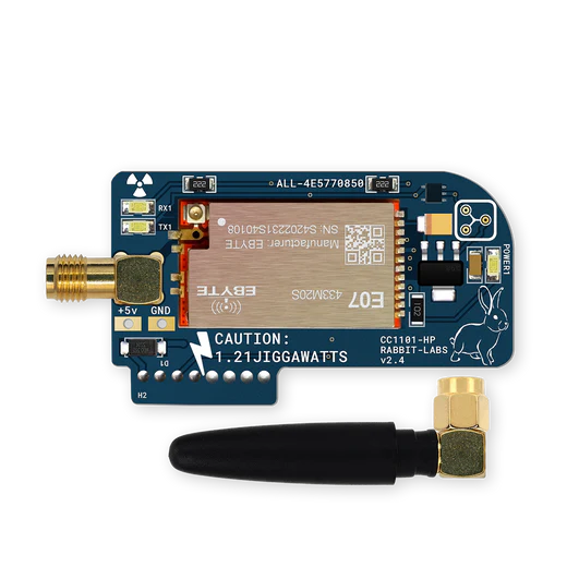
Component Configuration
Section titled “Component Configuration”# Minimal Examplecc1101: cs_pin: GPIOXX frequency: 433.92MHzConfiguration Variables
Section titled “Configuration Variables”Hardware Settings
Section titled “Hardware Settings”- cs_pin (Required, Pin): The SPI Chip Select (CSN) pin connected to the module.
- gdo0_pin (Optional, Pin):
The GDO0 pin. Required when
packet_modeis enabled, also used for single pin mode switching.
General Settings
Section titled “General Settings”- frequency (Optional, frequency): The operating frequency.
Range:
300MHzto928MHz. Defaults to433.92MHz. - output_power (Optional, float): The transmission power in dBm.
Range:
-30to11. Defaults to10. - modulation_type (Optional, enum): The modulation format.
Options:
ASK/OOK(default),2-FSK,4-FSK,GFSK,MSK. - symbol_rate (Optional, int): The symbol rate in Baud.
Range:
600to500000. Defaults to5000. - rx_attenuation (Optional, enum): Internal RX attenuation.
Options:
0dB,6dB,12dB,18dB. Defaults to0dB. - dc_blocking_filter (Optional, boolean): Enable the digital DC blocking filter. Defaults to
true. - manchester (Optional, boolean): Enable Manchester encoding. Defaults to
false.
Tuner Settings
Section titled “Tuner Settings”- filter_bandwidth (Optional, frequency): The receive filter bandwidth.
Range:
58kHzto812kHz. Defaults to203kHz. - fsk_deviation (Optional, frequency): Frequency deviation for FSK/GFSK modulation.
Range:
1.5kHzto381kHz. - msk_deviation (Optional, int): Deviation index for MSK modulation. Range:
1to8. - channel (Optional, int): Channel number (added to base frequency). Defaults to
0. - channel_spacing (Optional, frequency): Spacing between channels.
Range:
25kHzto405kHz. Defaults to200kHz. - if_frequency (Optional, frequency): Intermediate Frequency.
Range:
25kHzto788kHz. Defaults to153kHz.
Packet Mode Settings
Section titled “Packet Mode Settings”These settings enable the CC1101’s built-in packet handling with FIFO buffering, sync word detection, and optional CRC checking.
-
packet_mode (Optional, boolean): Enable FIFO packet mode. When enabled,
gdo0_pinis required. Defaults tofalse. -
packet_length (Required when
packet_modeis enabled, int or lambda): Packet length in bytes. Set to0for native variable length packets, where the first byte after the sync word is the length byte. Range:0to1024. As a lambda, it computes the received packet length from the bytes received so far, passed asx(std::vector<uint8_t>). Return a negative value to discard the current packet, return0while the length is still unknown, or return the full packet length in bytes, at most1024. A length that is not more than the bytes already received ends the packet there. The lambda must return the length before the last byte of the packet arrives: while the length is unknown, the last received byte stays in the RX FIFO, so a lambda that waits for the whole packet never sees it and the packet is discarded. Requirespacket_mode: true. -
crc_enable (Optional, boolean): Enable CRC-16 calculation and checking. The CC1101 uses CRC-16-IBM (polynomial 0x8005). Defaults to
false. Not available withpacket_lengthabove 64 or a lambda. -
whitening (Optional, boolean): Enable data whitening to improve DC balance. Defaults to
false. -
sync_mode (Optional, enum): Sync word detection mode. Options:
None,15/16,16/16,30/32. Defaults to16/16. -
sync0 (Optional, hex): Lower sync word byte. Defaults to
0x91. -
sync1 (Optional, hex): Upper sync word byte. Defaults to
0xD3. -
num_preamble (Optional, int): Number of preamble bytes to transmit. Range:
0to7(maps to 2, 3, 4, 6, 8, 12, 16, 24 bytes). Defaults to2(4 bytes).
NOTE
Packet lengths above 64 bytes and a packet_length lambda are supported for receive only. The receiver
drains the CC1101 RX FIFO while the packet is being received and uses the packet length handling described
in the CC1101 datasheet sections 15.2.1 and 15.2.2. Long packet reception depends on the ESPHome loop
draining the RX FIFO before it overflows. Long packet transmission is not implemented: with such a
packet_length, cc1101.send_packet is rejected.
AGC (Automatic Gain Control) Settings
Section titled “AGC (Automatic Gain Control) Settings”Advanced users can fine-tune the AGC dynamics. The AGC automatically adjusts receiver gain to handle signals of varying strength. These settings control how aggressively and quickly the gain adapts. See the CC1101 Datasheet for detailed information.
-
magn_target (Optional, dB): Target signal amplitude for the AGC loop. Higher values increase sensitivity but may cause clipping on strong signals. One of:
24dB27dB30dB33dB36dB38dB40dB42dB(default)
-
max_lna_gain (Optional, dB): Limits the maximum LNA (Low Noise Amplifier) gain. Use to prevent saturation in high-signal environments. Defaults to
Default. Options:Default,2.6dB,6.1dB,7.4dB,9.2dB,11.5dB,14.6dB,17.1dB. -
max_dvga_gain (Optional, enum): Limits the maximum DVGA (Digital Variable Gain Amplifier) gain. Options:
Default,-1,-2,-3. Defaults to-3. -
lna_priority (Optional, boolean): If true, reduce LNA gain before DVGA gain when decreasing overall gain. Useful for optimizing noise figure. Defaults to
false. -
carrier_sense_above_threshold (Optional, boolean): Only accept packets when carrier sense indicates a signal is present. Defaults to
false. -
carrier_sense_abs_thr (Optional, int): Absolute RSSI threshold for carrier sense. The radio considers a carrier present when RSSI exceeds this level. Range:
-8to7. -
carrier_sense_rel_thr (Optional, enum): Relative RSSI threshold for carrier sense, compared to the current noise floor. Options:
Default,+6dB,+10dB,+14dB. -
filter_length_fsk_msk (Optional, enum): Averaging length for AGC in FSK/MSK modes. Longer values provide more stable gain but slower response. Options:
8,16,32,64. -
filter_length_ask_ook (Optional, enum): Averaging length for AGC in ASK/OOK modes. Longer values provide more stable gain but slower response. Options:
4dB,8dB,12dB,16dB. -
freeze (Optional, enum): Controls when AGC gain is frozen (held constant). Options:
Default,On Sync,Analog Only,Analog And Digital. -
wait_time (Optional, enum): Time to wait after a gain change before allowing another adjustment. Options:
8,16,24,32. Defaults to32. -
hyst_level (Optional, enum): Hysteresis level to prevent gain oscillation on borderline signals. Options:
None,Low,Medium,High.
Frequency Offset and Bit Synchronization Settings
Section titled “Frequency Offset and Bit Synchronization Settings”Advanced users can tune how the receiver tracks frequency error and symbol timing error while demodulating FSK/MSK signals. These settings affect how quickly the demodulator adapts before and after sync word detection, and how much frequency or data rate offset it is allowed to compensate. When omitted, the datasheet power-on-reset defaults are used. Leave them unset unless you need protocol-specific receiver tuning.
- foc_bs_cs_gate (Optional, boolean): Freeze frequency offset compensation and clock recovery until carrier sense is asserted.
- foc_limit (Optional, enum): Saturation point for frequency offset compensation.
Options:
Disabled,BW/8,BW/4,BW/2. - foc_pre_k (Optional, enum): Frequency compensation loop gain before sync word detection.
Options:
K,2K,3K,4K. - foc_post_k (Optional, enum): Frequency compensation loop gain after sync word detection.
Options:
Same,K/2. - bs_limit (Optional, enum): Saturation point for data rate offset compensation.
Options:
Disabled,3.125%,6.25%,12.5%. - bs_pre_ki (Optional, enum): Clock recovery integral gain before sync word detection.
Options:
KI,2KI,3KI,4KI. - bs_pre_kp (Optional, enum): Clock recovery proportional gain before sync word detection.
Options:
KP,2KP,3KP,4KP. - bs_post_ki (Optional, enum): Clock recovery integral gain after sync word detection.
Options:
Same,KI/2. - bs_post_kp (Optional, enum): Clock recovery proportional gain after sync word detection.
Options:
Same,KP.
Frequency offset compensation is ignored for ASK/OOK modulation.
Triggers
Section titled “Triggers”on_packet Trigger
Section titled “on_packet Trigger”In packet mode, this trigger fires when a packet has been received. A variable x of type
std::vector<uint8_t> containing the packet data is passed to the automation. The following
variables are also available:
freq_offset: Frequency offset estimate in Hz.rssi: Signal strength in dBm.lqi: Link quality indicator (0-127, lower is better).
cc1101: cs_pin: GPIOXX gdo0_pin: GPIOXX frequency: 433.92MHz modulation_type: GFSK symbol_rate: 4800 packet_mode: true packet_length: 8 on_packet: then: - lambda: |- char hex[256]; // Size appropriately for your data ESP_LOGD("cc1101", "packet %s freq_offset %.0f Hz rssi %.1f dBm lqi %u", format_hex_to(hex, x), freq_offset, rssi, lqi);Actions
Section titled “Actions”cc1101.begin_tx Action
Section titled “cc1101.begin_tx Action”This action puts the radio into TX mode and switches gdo0_pin to output mode.
cc1101.begin_rx Action
Section titled “cc1101.begin_rx Action”This action puts the radio into RX mode and switches gdo0_pin to input mode.
cc1101.set_idle Action
Section titled “cc1101.set_idle Action”This action puts the radio into an idle state.
cc1101.power_down Action
Section titled “cc1101.power_down Action”This action puts the radio into SLEEP mode to reduce power consumption
when it is not in use. A sleeping radio receives nothing, so on_packet does not fire. Settings changed while it
sleeps are applied when it wakes up.
cc1101.wake_up Action
Section titled “cc1101.wake_up Action”This action wakes the radio from SLEEP mode into an idle state and restores the
settings lost in SLEEP, including the output-power table. cc1101.begin_tx, cc1101.begin_rx, cc1101.set_idle
and cc1101.send_packet also wake the radio on their own. To receive packets again after cc1101.wake_up,
follow it with cc1101.begin_rx.
For example, a transmit-only remote can sleep between commands; cc1101.begin_tx wakes it before each one:
esphome:  on_boot:    - priority: -100      then:        - cc1101.power_down
remote_transmitter:  pin: GPIOXX  # Must match GDO0  carrier_duty_percent: 100%  on_transmit:    then:      - cc1101.begin_tx  on_complete:    then:      - cc1101.power_down
cc1101.reset Action
Section titled “cc1101.reset Action”This action resets the CC1101 chip and re-applies configuration.
cc1101.send_packet Action
Section titled “cc1101.send_packet Action”This action transmits a packet. Only available when packet_mode is enabled.
Long packet transmission is not implemented.
Configuration variables
Section titled “Configuration variables”- data (Required, list, templatable): The packet to send. The packet
must fit into the CC1101 TX FIFO: up to 64 bytes in fixed length mode, where its length must match
packet_length, or up to 63 payload bytes in native variable length mode.
on_...: - cc1101.send_packet: data: [0x12, 0x34, 0x56, 0x78]cc1101.set_frequency Action
Section titled “cc1101.set_frequency Action”This action changes the operating frequency at runtime.
Configuration variables
Section titled “Configuration variables”- value (Required, frequency):
The frequency to set. Range:
300MHzto928MHz.
on_...: - cc1101.set_frequency: 433.92MHz - cc1101.set_frequency: value: !lambda "return 868.0e6;"cc1101.set_output_power Action
Section titled “cc1101.set_output_power Action”This action changes the transmission power at runtime.
Configuration variables
Section titled “Configuration variables”- value (Required, float): The output power in dBm. Range:
-30to11.
cc1101.set_modulation_type Action
Section titled “cc1101.set_modulation_type Action”This action changes the modulation type at runtime.
Configuration variables
Section titled “Configuration variables”- value (Required, enum): The modulation type.
Options:
ASK/OOK,2-FSK,4-FSK,GFSK,MSK.
on_...: - cc1101.set_modulation_type: "GFSK" - cc1101.set_modulation_type: value: !lambda |- return cc1101::Modulation::MODULATION_2_FSK;cc1101.set_symbol_rate Action
Section titled “cc1101.set_symbol_rate Action”This action changes the symbol rate at runtime.
Configuration variables
Section titled “Configuration variables”- value (Required, float): The symbol rate in baud. Range:
600to500000.
cc1101.set_rx_attenuation Action
Section titled “cc1101.set_rx_attenuation Action”This action changes the internal RX attenuation at runtime.
Configuration variables
Section titled “Configuration variables”- value (Required, enum): The attenuation level.
Options:
0dB,6dB,12dB,18dB.
on_...: - cc1101.set_rx_attenuation: "12dB" - cc1101.set_rx_attenuation: value: !lambda |- return cc1101::RxAttenuation::RX_ATTENUATION_0DB;cc1101.set_dc_blocking_filter Action
Section titled “cc1101.set_dc_blocking_filter Action”This action enables or disables the DC blocking filter at runtime.
Configuration variables
Section titled “Configuration variables”- value (Required, boolean):
trueto enable,falseto disable.
cc1101.set_manchester Action
Section titled “cc1101.set_manchester Action”This action enables or disables Manchester encoding at runtime.
Configuration variables
Section titled “Configuration variables”- value (Required, boolean):
trueto enable,falseto disable.
cc1101.set_filter_bandwidth Action
Section titled “cc1101.set_filter_bandwidth Action”This action changes the receive filter bandwidth at runtime.
Configuration variables
Section titled “Configuration variables”- value (Required, frequency):
The filter bandwidth. Range:
58kHzto812kHz.
cc1101.set_fsk_deviation Action
Section titled “cc1101.set_fsk_deviation Action”This action changes the FSK/GFSK frequency deviation at runtime.
Configuration variables
Section titled “Configuration variables”- value (Required, frequency):
The frequency deviation. Range:
1.5kHzto381kHz.
cc1101.set_msk_deviation Action
Section titled “cc1101.set_msk_deviation Action”This action changes the MSK deviation index at runtime.
Configuration variables
Section titled “Configuration variables”- value (Required, int): The deviation index. Range:
1to8.
cc1101.set_channel Action
Section titled “cc1101.set_channel Action”This action changes the channel number at runtime.
Configuration variables
Section titled “Configuration variables”- value (Required, int): The channel number. Range:
0to255.
cc1101.set_channel_spacing Action
Section titled “cc1101.set_channel_spacing Action”This action changes the channel spacing at runtime.
Configuration variables
Section titled “Configuration variables”- value (Required, frequency):
The spacing between channels. Range:
25kHzto405kHz.
cc1101.set_if_frequency Action
Section titled “cc1101.set_if_frequency Action”This action changes the intermediate frequency at runtime.
Configuration variables
Section titled “Configuration variables”- value (Required, frequency):
The intermediate frequency. Range:
25kHzto788kHz.
Integration with Remote Receiver/Transmitter
Section titled “Integration with Remote Receiver/Transmitter”For ASK/OOK modulation, the CC1101 integrates with Remote Receiver/Transmitter for protocol encoding and decoding. The component automatically configures the GDO pins to support both dual and single pin wiring schemes.
1. Dual Pin Wiring (Recommended)
Section titled “1. Dual Pin Wiring (Recommended)”This is the simplest and recommended wiring scheme. It uses separate pins for transmitting and receiving data.
- GDO0 (Module Pin 3): Connect to the MCU pin used by
remote_transmitter. - GDO2 (Module Pin 8): Connect to the MCU pin used by
remote_receiver.
cc1101:  cs_pin: GPIOXX
remote_transmitter:  pin: GPIOXX  # Must match GDO0  carrier_duty_percent: 100%  on_transmit:    then:      - cc1101.begin_tx  on_complete:    then:      - cc1101.begin_rx
remote_receiver:  pin: GPIOXX  # Must match GDO2  dump: all
2. Single Pin Wiring
Section titled “2. Single Pin Wiring”This wiring scheme uses a single MCU pin for both transmitting and receiving data, connected to GDO0.
This requires careful configuration of the remote_transmitter and remote_receiver to avoid conflicts.
- GDO0 (Module Pin 3): Connect to a single MCU GPIO pin.
- GDO2 (Module Pin 8): Leave disconnected.
Single Pin with Open-Drain
Section titled “Single Pin with Open-Drain”ESP32 must use this method when using single-pin wiring. The shared pin should be set to open-drain with a
pullup. The eot_level option (from remote_transmitter) controls the pin state after transmission
completes - setting it to false keeps the pin low until explicitly released. In addition to setting the
CC1101 mode in on_transmit/on_complete, the pin should be driven low before begin_tx and released
before begin_rx.
cc1101:  cs_pin: GPIOXX
remote_receiver:  pin:    number: GPIOXX  # Must match GDO0    mode:      input: true      output: true      pullup: true      open_drain: true    allow_other_uses: true  dump: all
remote_transmitter:  pin:    number: GPIOXX  # Must match GDO0    mode:      input: true      output: true      pullup: true      open_drain: true    allow_other_uses: true  eot_level: false  carrier_duty_percent: 100%  on_transmit:    then:      - cc1101.set_idle      - remote_transmitter.digital_write: false      - cc1101.begin_tx  on_complete:    then:      - cc1101.set_idle      - remote_transmitter.digital_write: true      - cc1101.begin_rx
Single Pin with Automatic Mode Switching
Section titled “Single Pin with Automatic Mode Switching”When gdo0_pin is configured, begin_tx and begin_rx automatically switch the pin between output
and input modes, simplifying the configuration.
cc1101:  cs_pin: GPIOXX  gdo0_pin:    number: GPIOXX  # Must match GDO0    allow_other_uses: true
remote_receiver:  pin:    number: GPIOXX  # Must match GDO0    allow_other_uses: true  dump: all
remote_transmitter:  pin:    number: GPIOXX  # Must match GDO0    allow_other_uses: true  carrier_duty_percent: 100%  on_transmit:    then:      - cc1101.begin_tx  on_complete:    then:      - cc1101.begin_rx
Troubleshooting
Section titled “Troubleshooting”“FF0F was found” Error
Section titled ““FF0F was found” Error”If you see a log entry stating FF0F, 0000, or FFFF during setup, this indicates an SPI
communication failure. Check your wiring (MISO/MOSI/CS).
No Signal During Transmit
Section titled “No Signal During Transmit”- Check Pinout: For all modes, the data line must be connected to GDO0 (Module Pin 3), as the CC1101 chip only supports transmission input via the GDO0 pin.
- Check Pin Mode: Ensure
gdo0_pinis configured for automatic pin mode switching.