

MiCS-5524 Gas Sensor
The mics_5524 sensor platform allows you to use the MiCS-5524 MEMS multi-gas sensor - the small 5 V
analog modules with VCC / GND / A0 / EN pads, and the DFRobot “Fermion” breakout they are cloned from - with
ESPHome. One entry configures one physical sensor: it reads the analog output once per update_interval and publishes
every gas listed under it as its own sub-sensor.
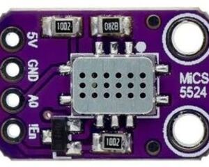
The module has a single analog output (AO) for several reducing gases. The component reads it either from an existing
voltage sampler such as an ADC or ADS1115 sensor
(voltage:), or through the adc sensor it creates itself when it is given the pin (pin:, with an optional
voltage_divider: and enable_pin:). It converts the sampled voltage with one of two conversion models and evaluates
the curve of every configured gas, so one reading is interpreted per gas instead of read once per gas.
NOTE
The MiCS-5524 is not a safety-grade sensor. It has one analog output for CO, H2, C2H5OH, NH3 and CH4 and cannot tell them apart, and individual sensors vary widely. Treat every published value as an estimate.
How the Numbers Are Calculated
Section titled “How the Numbers Are Calculated”The conversion: key selects the model of a sensor. dfrobot is the default vendor model this breakout is sold for;
datasheet uses the resistance model of the SGX data sheet.
Vendor Model (conversion: dfrobot)
Section titled “Vendor Model (conversion: dfrobot)”The component implements the model of the DFRobot_MICS library (MIT), which is what this breakout is sold for and what the Fermion tutorial uses:
xis how far the analog output sits below the supply andx_airis the same value in clean air, where the ratio is 1.0. The ratio drops as the gas concentration rises, and the ppm value follows from thethresholdandgainof the gas: a ratio above the threshold counts as “not detected” and publishes 0 ppm, a result below the vendor minimum of the gas is reported the same way, and the upper end is clamped to the measuring range of that gas.x_airis measured in place, either hard-coded withair_reference:or captured by the automatic clean-air calibration (calibration:), so the board’s load resistor and the exact divider ratio do not matter.
Datasheet Model (conversion: datasheet)
Section titled “Datasheet Model (conversion: datasheet)”The datasheet model works from the sensor resistance instead of the voltage drop:
RSis the sensor resistance in kΩ andRLthe load resistor in front of it (rl:,10kΩ by default).R0is the same resistance in clean air, where the ratio is 1.0 and falls as a reducing gas is present.R0is hard-coded withr0:or captured by the clean-air calibration (calibration:).- Only CO ships with a fit:
a = 1.0,b = -1.2, read off the sensitivity graph of SGX data sheet 1084 rev 8 with R0 at clean air, where the sensor sits at the 1 ppm bottom of its detection range. The data sheet calls its curve indicative - the sensitivity factor spans 1.2 to 50 between units. Every other gas needs bothcoefficient_a:andcoefficient_b:in its sub-sensor. coefficient_b:has to be negative: the resistance of a metal-oxide sensor falls as a reducing gas rises, so a flat or rising fit is rejected.
The two models share the per-gas min_ppm: / max_ppm: range, but not the reference keys: air_reference: is only
accepted with conversion: dfrobot, and rl:, r0: and rs_sensor: only with conversion: datasheet.
Example Configuration
Section titled “Example Configuration”The analog output is read through an ADC sensor. The 10k/20k divider of the recommended
wiring maps the 0 - 5 V output onto 0 - 3.33 V, which voltage_multiplier: 1.5 scales back:
# Example configuration entrysensor:  - platform: adc    id: mics_ao    pin: GPIOXX    attenuation: 12db
  - platform: mics_5524    voltage: mics_ao    voltage_multiplier: 1.5     # 10k/20k divider in front of the AO pin    calibration:                # capture the clean-air reference at boot      delay: 3min    carbon_monoxide:      name: "CO (MiCS-5524)"    hydrogen:      name: "H2 (MiCS-5524)"
Any other voltage sampler works the same way, for example an ADS1115 channel. Its inputs are limited to its own supply, so the divider stays unless the ADS1115 runs from 5 V. A fixed reference skips the calibration, which is what a stable, already burned-in sensor ends up with:
# Example configuration entry, external sampler and a fixed referencesensor:  - platform: ads1115    id: mics_ao    multiplexer: A0_GND    gain: 4.096
  - platform: mics_5524    voltage: mics_ao    voltage_multiplier: 1.5     # the same 10k/20k divider    air_reference: 1.2          # VCC - V_AO in clean air, from a previous calibration    carbon_monoxide:      name: "CO trace (MiCS-5524)"
The component can also create the adc sensor itself (pin:), take the divider from its resistors
(voltage_divider:) and switch the module on over EN. conversion: datasheet with r0: selects the datasheet
model, and the diagnostics make the intermediate values visible. On ESP32 the wiring check uses the measuring range
of the configured adc_attenuation: for the variant (about 2.45 V at the default 12db on the original ESP32), so
the 10k/20k divider of the vendor wiring does not fit a pin: source there; a 22k/20k divider brings the 5 V output
down to 2.38 V.
# Example configuration entry, component-owned ADC and the datasheet modelsensor: - platform: mics_5524 id: mics_5524 pin: GPIOXX voltage_divider: # 22k/20k brings the 5 V output down to 2.38 V on the pin r1: 22000 r2: 20000 conversion: datasheet r0: 10.0 # RS in clean air, in kOhm enable_pin: # EN of the module is active low number: GPIOXX inverted: true voltage_sensor: name: "MiCS-5524 voltage" ratio_sensor: name: "MiCS-5524 ratio" carbon_monoxide: name: "CO (MiCS-5524)"NOTE
Keep the sensor in clean air for the whole calibration and do not configure a gas that may be present while it runs: the reference it captures is the baseline of every later reading.
Configuration Variables
Section titled “Configuration Variables”One entry is one physical sensor and not an entity itself: the gases listed under it are the entities.
Front End
Section titled “Front End”Exactly one source of the analog output is required:
- voltage (Optional, ID): The ID of a voltage sampler (
adc,ads1115, …) that reads the AO pin. Exactly one ofvoltage:andpin:is required. - pin (Optional, Pin): The pin the AO output is connected to. The component
creates the
adcsensor it reads from and averagessample_count:conversions of it per reading. Exactly one ofvoltage:andpin:is required. - voltage_multiplier (Optional, float): The multiplier applied to the sampled voltage, the inverse of the
divider ratio (
1.5for a 10k/20k divider,1.0for a directly connected sensor or a sampler with a wider input range). Defaults to1.0. Mutually exclusive withvoltage_divider:. - voltage_divider (Optional): The resistor divider in front of the pin, from which the multiplier is derived as
(r1 + r2) / r2. Mutually exclusive withvoltage_multiplier:.- r1 (Required, float): The resistor between AO and the pin, in Ohm.
- r2 (Required, float): The resistor between the pin and ground, in Ohm.
- adc_input_max (Optional, float): The top of the measuring range of the sampler, in volts: the largest reading
the wiring can produce (
vcc:scaled byvoltage_divider:orvoltage_multiplier:) has to stay within it, and a 10 mV margin is allowed. Defaults to the built-in limit of the platform (ESP32 and RP23.3, ESP82661.0); for an ESP32pin:source it defaults to the range of the configuredadc_attenuation:instead. On a platform without a built-in limit both this andadc_pin_max:are required as soon as the wiring is checked. - adc_pin_max (Optional, float): The absolute maximum the ADC pin tolerates, in volts; it is checked the same
way as
adc_input_max:. Defaults to the built-in limit of the platform (ESP32 and RP23.6, ESP82661.0). - adc_attenuation (Optional, enum): The attenuation of the
adcsensor thatpin:creates:0db,2.5db,6db,11db,12dborauto. Defaults to12dbon ESP32 so the pin is not clipped by the 0 dB default, and it also picks the defaultadc_input_max:of the wiring check there. Withvoltage:setattenuation:on that sampler instead. - enable_pin (Optional, Pin): The pin wired to the
ENpad of the module. The input is active low, so configureinverted: true, or the module stays asleep and every reading sits at 0 V.
Every pin: source is checked against these limits, so wiring that puts the full vcc: on the ADC is rejected unless
a voltage_divider: or voltage_multiplier: scales it down. A voltage: source is only checked when it has a
voltage_divider:, since the scaling of an external sampler is not known here. adc_input_max: and adc_pin_max:
are accepted only together with pin: or voltage_divider:.
Conversion Model and Reference
Section titled “Conversion Model and Reference”- conversion (Optional, enum): The conversion model of the sensor,
dfrobot(default) ordatasheet. See How the Numbers Are Calculated. - vcc (Optional, float): The supply voltage of the module. A reading above it cannot come from the sensor,
so it is reported as
unknownwith a warning instead of being published as a measurement. Defaults to5.0. - air_reference (Optional, float): The fixed clean-air reference of the vendor model in volts (
VCC - V_AOmeasured in clean air). It has to be smaller thanvcc:, skips the calibration at boot, and is mutually exclusive withcalibration:andr0:. Only accepted withconversion: dfrobot. - rl (Optional, float): The load resistor
RLof the datasheet model, in kΩ. Defaults to10. Only accepted withconversion: datasheet. - r0 (Optional, float):
RSin clean air, in kΩ, of the datasheet model. It skips the calibration at boot and is mutually exclusive withcalibration:andair_reference:. Only accepted withconversion: datasheet.
Sampling
Section titled “Sampling”- sample_count (Optional, int): The number of AO conversions averaged per reading. They run back to back inside
one pass of the main loop. Defaults to
4. Range: 1-16. - warmup_time (Optional, Time): The heater warm-up. Nothing is published
before it has elapsed. Defaults to
3min; use24hfor the burn-in of a new module. - update_interval (Optional, Time): The interval between two readings,
shared by every gas of the entry. Defaults to
30s.
Calibration
Section titled “Calibration”- calibration (Optional): Capture the clean-air reference at boot instead of hard-coding it (
air_reference:orr0:). At most one ofcalibration:,air_reference:andr0:may be set.- delay (Optional, Time): The time to wait after boot before the first
sample, so the module has settled. Defaults to
60s. - sample_count (Optional, int): The number of readings averaged into the reference. Defaults to
10. Range: 2-16. - sample_interval (Optional, Time): The spacing between two of those
readings. Defaults to
20ms; the minimum is 16 ms, one pass of the main loop. - persist (Optional, boolean): Store the captured reference in flash so it survives a reboot. Defaults to
true.
- delay (Optional, Time): The time to wait after boot before the first
sample, so the module has settled. Defaults to
Without calibration:, air_reference: or r0: the component has no reference at boot, so every gas stays unknown
until one is captured with the mics_5524.request_calibration action.
Diagnostics
Section titled “Diagnostics”- voltage_sensor (Optional, Sensor): The averaged, scaled AO voltage in V.
- ratio_sensor (Optional, Sensor): The conversion ratio,
x / x_airin the vendor model andRS / R0in the datasheet model. - rs_sensor (Optional, Sensor): The sensor resistance
RSin kΩ. Only accepted withconversion: datasheet.
Gas Sub-Sensors
Section titled “Gas Sub-Sensors”carbon_monoxide, hydrogen, ethanol, ammonia and methane are the gases of the platform, and at least one of
them has to be configured. Each one is a normal Sensor, so name:, id:, filters:,
accuracy_decimals:, unit_of_measurement: and everything else from that platform apply, plus:
- max_ppm (Optional, float): The upper end of the published range, which has to be above
min_ppm:. Defaults to the range of the gas: the fitted range of the shipped CO datasheet fit, otherwise the vendor range (also for a datasheet gas with user coefficients). In the vendor model it may narrow that range but not raise it. - min_ppm (Optional, float): Readings below it are published as
0 ppm(not detected). Defaults to the floor of the gas: its vendor minimum, or, in the datasheet model, the1ppm bottom of the shipped CO fit and0for a gas with user coefficients. Must be0or greater, and smaller thanmax_ppm:. - coefficient_a / coefficient_b (Optional, float): The
aandbof the datasheet power law of this gas. Both have to be set together, andcoefficient_b:has to be negative. They replace the shipped fit; the gases without one require them. Only accepted withconversion: datasheet.
| Sub-sensor | Vendor range | Vendor threshold | Vendor gain | Datasheet a / b |
|---|---|---|---|---|
carbon_monoxide (CO) | 1 - 1000 ppm | 0.425 | 0.000405 | 1.0 / -1.2 |
hydrogen (H2) | 1 - 1000 ppm | 0.279 | 0.00026 | - |
ammonia (NH3) | 10 - 500 ppm | 0.8 | 0.0015 | - |
ethanol (C2H5OH) | 10 - 500 ppm | 0.306 | 0.00057 | - |
methane (CH4) | 1000 - 25000 ppm | 0.786 | 0.000023 | - |
- The vendor
thresholdis the ratio relative to clean air (1.0) at or below which the gas counts as detected, andgainis the ratio drop per ppm, soppm = (threshold - ratio) / gain. - The vendor’s own minimum applies near the threshold: H2 and CO report 0 ppm below 1 ppm, NH3 and C2H5OH below 10 ppm and CH4 below 1000 ppm.
Actions
Section titled “Actions”mics_5524.request_calibration Action
Section titled “mics_5524.request_calibration Action”Capture a new clean-air reference at run time on the component with the given ID. The calibration starts once the
warm-up window has passed and uses the calibration: parameters (their defaults when no calibration: block is set).
The result replaces the reference in use. It is stored in flash and survives a reboot only when a calibration: block
is set and calibration.persist: is true; without a calibration: block it is kept until the next reboot.
- id (Required, ID): The ID of the
mics_5524sensor to calibrate.
# Example actionbutton: - platform: template name: "Calibrate MiCS-5524" on_press: - mics_5524.request_calibration: mics_5524Notes and Limitations
Section titled “Notes and Limitations”- Cross-sensitivity: The MiCS-5524 is a MEMS metal-oxide sensor for trace detection, not a safety device. The five sub-sensors are views of the same reading interpreted through the curve of their gas, not independent measurements. Both conversion models are affected.
unknownvs0 ppm: Unusable readings - an AO that cannot be read or is bottomed out near 0 V, a reading above the configuredvcc:, and a reference that is not available yet - publishunknown, never0 ppm, so a broken sensor cannot look like clean air. The component raises its status warning and logs the voltage once instead.0 ppmis only published when the model says “not detected”: the ratio is above the threshold, or the result is below the minimum of the gas.- The calibration has to be plausible: A run whose samples disagree by more than 25 % of their mean was not taken
in clean, still air, and neither was a run in which a majority of the samples were unusable. Both are logged with
the reason, are retried after
calibration.delayand keep the gasesunknownin the meantime. A new module needs 24 - 48 h of burn-in before its readings are stable. - The reference is stored in flash: With
calibration:the captured reference is kept in flash (calibration.persist:,trueby default) and restored at every boot, so a reboot does not need a new clean-air window. The stored value is keyed to the component ID, the conversion model,vcc:, the scaling andrl:, so changing one of them forces a new calibration. Hard-code the value the log reports asair_reference: ...(orr0: ...) to skip the calibration at boot. - A request overrides a fixed reference only until reboot:
calibration:cannot be combined withair_reference:orr0:, so a fixed reference is never persisted. Themics_5524.request_calibrationaction still captures and uses a new reference, but the configured value is back after the next reboot. - ESP32 ADC: The ESP32 ADC is noisy and bottoms out around 75 mV. Raise
sample_count, add an RC filter or use an ADS1115 behind the same divider. - Accuracy: The vendor model is a coarse fit of a multi-gas sensor, and the datasheet calls its own curve indicative, so the published ppm value estimates the concentration of the selected gas rather than measuring it.
Troubleshooting
Section titled “Troubleshooting”| Symptom | Likely cause |
|---|---|
state stays unknown, warning about a missing reference | no calibration: block and no air_reference: (vendor) or r0: (datasheet) |
analog output out of range status warning, reading 0.0000 V | AO not wired, module not powered or the EN pad not driven low (enable_pin: without inverted: true) |
analog output out of range status warning, reading above vcc: | wrong vcc: or voltage_multiplier: - the reading is ignored instead of published |
configuration error about adc_input_max: or adc_pin_max: | the keys are only checked for a pin: source or a voltage_divider:, so remove them or switch to one of those |
| configuration error that the wiring is above the ADC limit | the largest reading (vcc: scaled by the divider or voltage_multiplier:) exceeds adc_input_max:/adc_pin_max: - change the divider so less voltage reaches the pin (raise r1 relative to r2), then set voltage_divider: or voltage_multiplier: to match the new wiring; declare adc_input_max:/adc_pin_max: only for a sampler that really measures more |
| configuration error that a gas has no built-in datasheet coefficients | set both coefficient_a: and coefficient_b: for that gas |
| ppm far too high or too low in the datasheet model | wrong rl: or r0: - R0 is RS in clean air, in kΩ |
| ppm far too high | a reference that was captured while gas was present, or a divider ratio that does not match the wiring |
| ppm always 0 while gas is clearly present | the ratio stays above the gas’s threshold (0.425 for CO, 0.279 for H2), or the result is below the gas’s minimum (1 ppm for CO and H2, 10 ppm for NH3 and C2H5OH, 1000 ppm for CH4) - the model reports 0 ppm either way, so this is expected at low concentrations and not a calibration fault |
| values jump around | ESP32 ADC noise - raise sample_count or add an RC filter |
calibration failed, or a warning about the spread of the samples | the sensor was not settled in clean, still air; let it burn in and let the component retry |
| nothing is published for minutes after a restart | the warmup_time (3min by default); on a boot without a stored reference, max(warmup_time, calibration.delay) plus the calibration run itself; lower them while testing, or hard-code air_reference:/r0: |
TIP
The chain behind every reading (V_AO, the model value - x or RS - the ratio and the ppm value of each gas)
is logged at DEBUG, the default logger level, which is the quickest way to see whether the reading or its
reference is off.