

Hörmann Cover
The hoermann_hcp component allows you to control Hörmann garage door motors through the HCP bus built
into the motor. It emulates the Hörmann UAP1 module, so the motor’s bus controller communicates
with ESPHome just like it would with Hörmann’s own accessory.
The following Series 4 motors communicate over the HCP bus (Modbus RTU) and should be supported:
- SupraMatic E/P Series 4
- ProMatic Series 4
NOTE
Only Series 4 motors are supported. Older motors use a different connector pinout and a completely different protocol.
This component implements the same protocol as the HCPBridge project and is based on 14yannick’s ESPHome port.
CAUTION
HCP2 accessories are not hot-pluggable!
Disrupting Modbus connectivity for any reason may render the motor temporarily inoperable.
If this happens, the motor will be unresponsive to all controls in this error state, including BiSecur hand remotes. Ensure you have emergency access to your garage at all times, as this type of error can only be cleared by power-cycling the motor.
IMPORTANT
Restarting the ESPHome device (including OTA updates) will trigger the motor error described above.
Communication with the motor happens over Modbus with the role set to
server, which in turn requires a UART bus. The UART must be configured with
a baud rate of 57600, even parity and one stop bit.
# Example configuration entryuart:  id: uart_bus  tx_pin: GPIOXX  rx_pin: GPIOXX  baud_rate: 57600  parity: EVEN  stop_bits: 1
modbus:  uart_id: uart_bus  role: server
hoermann_hcp:
cover:  - platform: hoermann_hcp    name: Garage Door    device_class: garage
Hardware
Section titled “Hardware”The HCP bus is a two-wire RS485 connection that also carries the motor’s ~25 V supply, so a single cable provides both communication and power — no separate power supply is required. To connect an ESP32 (or another ESPHome-supported chip) you need four things:
- an RJ12 plug and cable to connect to the motor’s 6-pin bus socket;
- an RS485 transceiver wired to the UART bus;
- a step-down (buck) converter that derives 5 V for the ESP32 from the bus voltage (e.g. LM2596S); and
- a 120 Ω termination resistor across the RS485 data lines, as required by the RS485/Modbus standard.
The motor exposes the bus on a 6-pin socket with the following pinout:
| Pin | Signal | Example wire colour |
|---|---|---|
| 1 | GND | Black |
| 2 | GND | — |
| 3 | B− (RS485 data) | Yellow |
| 4 | A+ (RS485 data) | Grey |
| 5 | +25 V | Purple |
| 6 | +25 V | — |
NOTE
The wire colours depend on the cable you use — the pin positions are what matter. The GND (pins 1 and 2) and +25 V (pins 5 and 6) contacts are each duplicated on the motor side, so you only need to connect one pin from each pair (the diagram uses pins 1 and 5).
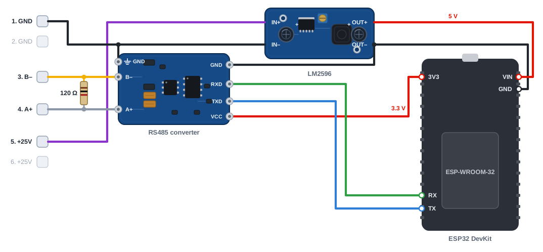
Wire the adapter as shown below: a +25 V pin feeds the buck converter’s input and its 5 V output
powers the ESP32, whose 3.3 V rail in turn supplies the RS485 transceiver. The A+/B− data lines
connect to the transceiver (with the 120 Ω resistor bridging them), and the transceiver’s serial pins
connect to the ESP32 UART pins you set in the uart: block.
IMPORTANT
Power the transceiver from the ESP32’s 3.3 V rail, not from the buck converter’s 5 V output. The
ESP32’s GPIOs are not 5 V tolerant, so a 5 V-powered transceiver would drive its receiver output
above what the rx_pin can safely accept.
NOTE
The example above uses a transceiver module with automatic direction control, so no separate DE/RE
flow-control pin is needed. If your module has a DE/RE pin instead, connect it to a spare GPIO and
set flow_control_pin on the UART bus — that option is ESP32-only, so on other
platforms set it on the Modbus component instead. If your module labels its
serial pins differently, connect its receiver output (RO/RXD) to the ESP32 rx_pin and its driver
input (DI/TXD) to the ESP32 tx_pin; swap the two if data doesn’t flow.
IMPORTANT
The adapter gets no power until a bus scan is run on the motor. The +25 V on the bus stays switched off until then, and the motor keeps it on only if the emulated UAP1 answers during the scan — otherwise it cuts the power again.
After wiring the adapter to the bus, trigger a bus scan from the motor’s menu to power it up and let the motor detect it. This is usually done by flicking the bottommost switch in the motor on and off again. Repeat the bus scan procedure (on/off) if something goes wrong, or before you disconnect the adapter.
Component/Hub
Section titled “Component/Hub”The hoermann_hcp hub handles the communication with the motor’s bus controller and exposes its state
to the cover platform below.
Configuration variables
Section titled “Configuration variables”- id (Optional, ID): Manually specify the ID used for code generation.
- modbus_id (Optional, ID): Manually specify the ID of the Modbus hub.
- address (Optional, int): The Modbus server address the component answers on. Defaults to
2, which is the address the motor’s bus controller expects the UAP1 module on. You should not need to change this. - update_interval (Optional, Time): The interval at which
the connection to the bus controller is checked and state changes are published. Raising it delays
every door state update by the same amount. Defaults to
500ms.
The hoermann_hcp cover platform exposes the garage door as a cover. It supports
opening, closing, stopping and moving to a position, and reports the position and operation as
provided by the motor.
cover: - platform: hoermann_hcp name: Garage Door device_class: garageConfiguration variables
Section titled “Configuration variables”- hoermann_hcp_id (Optional, ID): Manually specify the ID of the
hoermann_hcphub. Only required if you have more than one hub. - All other options from Cover.
Button
Section titled “Button”The hoermann_hcp button platform exposes the motor’s built-in vent and half-open commands.
button: - platform: hoermann_hcp vent: name: Garage Vent half_open: name: Garage Half OpenConfiguration variables
Section titled “Configuration variables”- hoermann_hcp_id (Optional, ID): Manually specify the ID of the
hoermann_hcphub. Only required if you have more than one hub. - vent (Optional): Configuration for the vent button. When pressed, moves the door to its built-in vent position.
- half_open (Optional): Configuration for the half-open button. When pressed, moves the door to its built-in half-open position.
Both buttons support all options from Button.
The hoermann_hcp light platform controls the courtesy light built into the motor. It is an on/off
light and follows the state reported by the motor, so it also updates when the light is switched by
the motor itself — for example when it turns on while the door moves.
NOTE
The light only accepts commands once the motor has reported the lamp state. Until then, the entity is flagged and switching it has no effect.
light: - platform: hoermann_hcp name: Garage LightConfiguration variables
Section titled “Configuration variables”- hoermann_hcp_id (Optional, ID): Manually specify the ID of the
hoermann_hcphub. Only required if you have more than one hub. - All other options from Light, except
restore_mode, which has no effect because the lamp state always comes from the motor.
Binary Sensor
Section titled “Binary Sensor”The hoermann_hcp binary sensor platform exposes diagnostic information about the connection to the
motor’s bus controller.
binary_sensor: - platform: hoermann_hcp is_connected: name: Garage ConnectedConfiguration variables
Section titled “Configuration variables”-
hoermann_hcp_id (Optional, ID): Manually specify the ID of the
hoermann_hcphub. Only required if you have more than one hub. -
is_connected (Required):
truewhile the motor’s bus controller is polling the emulated UAP1 module. Turnsfalseabout two seconds after the motor stops responding, for example after the bus power is cut. Defaults to theconnectivitydevice class and thediagnosticentity category, so the entity appears under the device’s diagnostics rather than on its main card. -
All options from Binary Sensor.
Text Sensor
Section titled “Text Sensor”The hoermann_hcp text sensor platform reports the door state as the motor names it, and the motor’s
serial number and firmware version.
text_sensor: - platform: hoermann_hcp door_state: name: Garage Door State serial_number: name: Garage Motor Serial Number version: name: Garage Motor Firmware VersionConfiguration variables
Section titled “Configuration variables”-
hoermann_hcp_id (Optional, ID): Manually specify the ID of the
hoermann_hcphub. Only required if you have more than one hub. -
door_state (Optional): The door state reported by the motor. Unlike the cover, it tells the vent and half-open positions apart. A new value is published only when the state changes. While the bus controller is not connected, the last value stays; the binary sensor shows whether it is current. The possible values are:
Value Meaning OpenFully open OpeningMoving to fully open ClosedFully closed ClosingMoving to fully closed Half openResting in the half-open position Moving to halfMoving to the half-open position Vent positionResting in the vent position Moving to ventMoving to the vent position StoppedStopped anywhere else -
serial_number (Optional): The motor’s serial number. It is requested once after the device starts and appears a moment later. If the motor does not send it after three attempts, 30 seconds apart, it stays unknown and a warning is logged. Defaults to the
diagnosticentity category. -
version (Optional): The motor’s firmware version, requested the same way. Defaults to the
diagnosticentity category. -
All options from Text Sensor.
NOTE
The cover shows the half-open position, the vent position and a stopped door all as open, each with its
position. Use door_state when an automation needs to tell these apart.
See Also
Section titled “See Also”- Cover Component
- Button Component
- Binary Sensor Component
- Light Component
- Text Sensor Component
- Modbus
- HCPBridge project
- Automation
- API Reference: hoermann_hcp_cover.h
- API Reference: hoermann_hcp_button.h
- API Reference: hoermann_hcp_light.h
- API Reference: hoermann_hcp_binary_sensor.h
- API Reference: hoermann_hcp_text_sensor.h