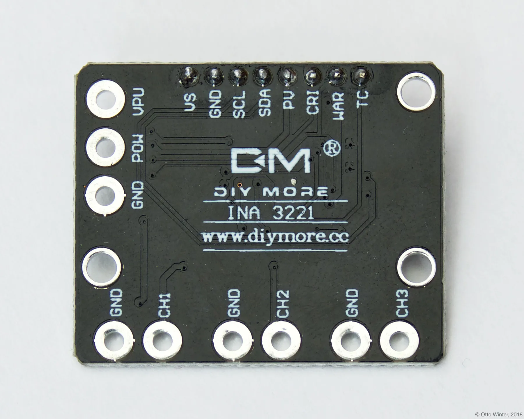
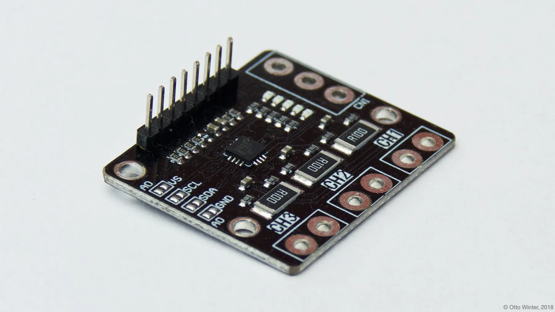
INA3221 3-Channel DC Current Sensor
The ina3221 sensor platform allows you to use your INA3221 3-Channel DC Current Sensor
(datasheet,
switchdoc) sensors with
ESPHome. The I²C Bus is
required to be set up in your configuration for this sensor to work.
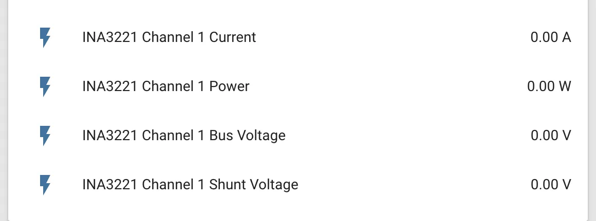
# Example configuration entrysensor: - platform: ina3221 address: 0x40 channel_1: shunt_resistance: 0.1 ohm current: name: "INA3221 Channel 1 Current" power: name: "INA3221 Channel 1 Power" bus_voltage: name: "INA3221 Channel 1 Bus Voltage" shunt_voltage: name: "INA3221 Channel 1 Shunt Voltage" channel_2: # ... channel_3: # ... update_interval: 60s# Single-shot mode with averaging, alert limits and the shunt voltage sumsensor: - platform: ina3221 continuous_mode: false adc_averaging: 16 adc_time: 1100us channel_1: shunt_resistance: 0.05 ohm current: name: "Channel 1 Current" warning_current_limit: 2.5A critical_current_limit: 3A channel_2: shunt_resistance: 0.05 ohm current: name: "Channel 2 Current" sum_shunt_voltage: name: "Sum Shunt Voltage" sum_current: name: "Total Current" update_interval: 60sConfiguration variables
Section titled “Configuration variables”-
address (Optional, int): Manually specify the I²C address of the sensor. Defaults to
0x40. -
channel_1 (Optional): The configuration options for the 1st channel.
-
shunt_resistance (Optional, float): The value of the shunt resistor on this channel for current calculation. Defaults to
0.1 ohm. -
current (Optional): Use the current value on this channel in amperes. All options from Sensor.
-
power (Optional): Use the power value on this channel in watts. All options from Sensor.
-
bus_voltage (Optional): Use the bus voltage (voltage of the high side contact) value on this channel in V. All options from Sensor.
-
shunt_voltage (Optional): Use the shunt voltage (voltage across the shunt resistor) value on this channel in V. All options from Sensor.
-
warning_current_limit (Optional, current): Current at which the chip pulls its WARNING pin low for this channel, for example
2.5A. The pin follows the averaged measurement. -
critical_current_limit (Optional, current): Current at which the chip pulls its CRITICAL pin low for this channel, for example
3A. The pin follows every single conversion.
-
-
channel_2 (Optional): The configuration options for the 2nd channel. Same options as 1st channel.
-
channel_3 (Optional): The configuration options for the 3rd channel. Same options as 1st channel.
-
continuous_mode (Optional, boolean): Keep the chip converting all the time. Set to
falsefor single-shot mode, where one conversion of every channel is started at each update and the chip idles in between. Defaults totrue. -
adc_averaging (Optional, int): Number of samples averaged per conversion. One of
1,4,16,64,128,256,512or1024. Defaults to1. -
adc_time (Optional, Time): Conversion time per sample. One of
140us,204us,332us,588us,1100us,2116us,4156usor8244us. Defaults to8244us. To use different times for the two measurements, give a mapping instead; each sub-key defaults to8244us:adc_time:bus_voltage: 1100usshunt_voltage: 4156us -
sum_shunt_voltage (Optional): The chip’s own sum of the shunt voltages of all configured channels, in V. It only tracks the total current when every configured channel has the same
shunt_resistance. All options from Sensor. -
sum_current (Optional): Sum of the currents of all configured channels, in amperes, added up from the per-channel readings with each channel’s own shunt. All options from Sensor.
-
sum_power (Optional): Sum of the power of all configured channels, in watts, added up from the per-channel readings. All options from Sensor.
-
update_interval (Optional, Time): The interval to check the sensor. Defaults to
60s. In single-shot mode it has to be longer than one conversion of all channels, which is(bus time + shunt time) × adc_averaging × configured channelsrounded up to whole milliseconds, plus 5 ms of headroom; the configuration fails otherwise.
The chip is put into power-down mode when the device shuts down or enters deep sleep, so a battery-powered node does not keep it converting.