

INA226 DC current and power sensor
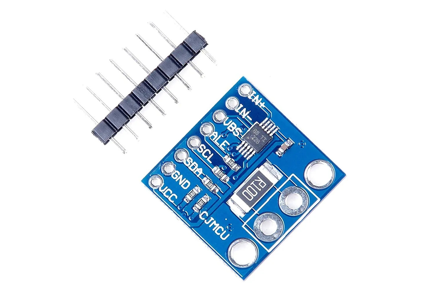
The ina226 sensor platform allows you to use your INA226 DC Current and Power Sensor
(datasheet, eBay) sensors with ESPHome.
The I²C Bus is required to be set up in your configuration for this sensor to work.
# Example configuration entrysensor: - platform: ina226 address: 0x40 shunt_resistance: 0.1 ohm max_current: 3.2A # adc time used for both, Bus Voltage and Shunt Voltage adc_time: 140us adc_averaging: 128 update_interval: 60s current: name: "INA226 Current" power: name: "INA226 Power" bus_voltage: name: "INA226 Bus Voltage" shunt_voltage: name: "INA226 Shunt Voltage"# Example configuration entrysensor: - platform: ina226 address: 0x40 adc_time: voltage: 140us current: 332usConfiguration variables
Section titled “Configuration variables”-
address (Optional, integer): Manually specify the I²C address of the sensor. Defaults to
0x40. -
shunt_resistance (Optional, float): The value of the shunt resistor on the board for current calculation. Defaults to
0.1 ohm. -
max_current (Optional, float): The maximum current you are expecting. ESPHome will use this to configure the sensor optimally. Defaults to
3.2A. -
adc_time (Optional, Time or both of the following nested options): The time in microseconds to perform a single ADC conversion. Defaults to
1100us. Valid values are140us,204us,332us,588us,1100us,2116us,4156us,8244us. -
adc_averaging (Optional, integer): Selects ADC sample averaging count. Defaults to
4. Valid values are1,4,16,64,128,256,512,1024. -
update_interval (Optional, Time): The interval to check the sensor. Defaults to
60s. -
alert (Optional): Drives the ALERT pin of the INA226 when a reading crosses a limit, or when a new measurement is ready. Without it the pin stays unused.
- function (Optional, string): What triggers the alert. Defaults to
none.none: no limit; setconversion_ready: trueto get only the conversion ready signal.shunt_over,shunt_under: the shunt voltage goes above or belowlimit.bus_over,bus_under: the bus voltage goes above or belowlimit, from0Vto36V.power_over: the power goes abovelimit.
- limit (Required for every function except
none, voltage or power): The threshold. Use a voltage such as75mVfor the shunt and bus functions, and a power such as5Wforpower_over. A plain number is read as volts or watts. For a current threshold, multiply it byshunt_resistance: 0.75A through a 0.1 Ω shunt is75mV. A value the chip cannot store with the configuredshunt_resistanceandmax_currentis rejected when the configuration is validated. - conversion_ready (Optional, boolean): Also assert the pin when a new measurement is ready.
Clear this signal with the
ina226.clear_alertaction to allow the next measurement to assert it again, even whenlatchisfalse. Reading the sensor values does not clear it. Defaults tofalse. - active_high (Optional, boolean): Drive the pin high when the alert is active, instead of low.
Defaults to
false. - latch (Optional, boolean): Keep the pin asserted until the alert is cleared with the
ina226.clear_alertaction, instead of releasing it when the reading returns within the limit. Defaults tofalse.
- function (Optional, string): What triggers the alert. Defaults to
The ALERT pin is open drain, so it needs a pull-up resistor; the internal pull-up of the input works.
Watch it with a GPIO Binary Sensor. inverted: true below matches the
default active-low output; drop it if you set active_high: true.
binary_sensor:  - platform: gpio    name: "INA226 Alert"    pin:      number: GPIOXX      inverted: true      mode:        input: true        pullup: true
sensor:  - platform: ina226    id: ina226_sensor    shunt_resistance: 0.1 ohm    max_current: 3.2A    power:      name: "Power"    alert:      function: power_over      limit: 5W      latch: true
The example uses a 5W limit for a 12V bus. Choose the power limit for your actual shunt resistance and
bus voltage. With the 0.1 ohm shunt above,
the INA226’s approximately 81.92mV shunt input range limits measurable current to about 0.819A, or 29.5W
at the maximum 36V bus voltage. Increasing max_current changes the measurement scaling, not this input
range. Use a lower power limit at lower bus voltages.
Sensors
Section titled “Sensors”The component offers four sensors. You can configure all or any subset of them. Each configured sensor
is reported separately on each update_interval. The name option is required for each sensor configured.
All other options from Sensor.
- current (Optional): Calculated current output, Amperes.
- power (Optional): Calculated power output, Watts.
- bus_voltage (Optional): Bus voltage output (voltage of the high side contact), Volts.
- shunt_voltage (Optional): Shunt voltage (voltage across the shunt resistor) value of the sensor, Volts.
ina226.clear_alert Action
Section titled “ina226.clear_alert Action”Reads the chip’s Mask/Enable register to release a latched alert and clear the conversion ready signal.
Use this action to acknowledge conversion ready alerts even when latch is false.
on_...: then: - ina226.clear_alert: ina226_sensor- id (Required, ID): The ID of the INA226 sensor.